Pattern
(This option is also available on the Drillhole | Planning tab, in the Planning group, when Drillhole Planning mode is active.)
![]()
Define Pattern
Click the Edit Extents button to collapse the form and interactively adjust the extents and the orientation of the pattern. The corresponding values in the Define Pattern group of the form will be updated.
Pick point in Vizex
Click the Pick point in Vizex button in the Define Pattern group, to interactively pick the coordinates of the East and North origin. The East and North origin values in the form will be updated.
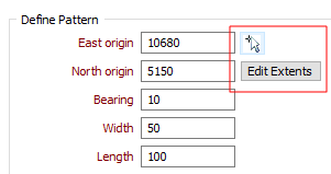
East and North origin
Enter the East origin and the North origin of the pattern (this point represents the South-West corner of the pattern).
Bearing
Enter a Bearing from zero degrees (North) to orient the pattern to the geology or any previous surveys. When looking along the bearing the origin is always in the bottom-left corner, drill lines run from left to right, and each new line is further from the origin, as shown in the diagram below:
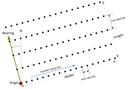
Width
Enter the width of the pattern (see diagram above).
Length
Enter the distance from the origin on which to calculate holes. This is measured in the direction of the bearing (see diagram above).
Hole spacing
Define the spacing between the holes along each line.
Line spacing
Define the spacing between the lines in the direction of the origin.
Edit Extents
Click the Edit Extents button to collapse the form and visually adjust the extents of the pattern. Interactively adjusting the extents rectangle in Vizex will update the values in the form.
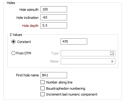
Holes
Define the Azimuth, Inclination, and Depth that will be applied to the holes.
The Hole azimuth is a bearing in degrees, measured from 0 for North and increasing clockwise. It will have no effect on a vertical hole (inclination of - 90).
The Hole inclination is the angle the hole makes with the azimuth, in the range 0 (horizontal) to - 90 (vertical). If no values are specified, a default inclination of -90 (vertical) and a default azimuth of zero are used.
Z values
Specify whether the elevation (Z values) of the holes are constant or variable values obtained from a DTM. If you have chosen the Constant option, enter the elevation (Z value) of the holes that will be created.
If you have chosen the From DTM option:
- Double-click or click on the Select icon to select a DTM Type.
- Double-click or click on the List icon to select the Name of the DTM.
Hole Numbering
First hole name
Specify how the first hole name will be incremented in the direction of the bearing (the default) or along each line (when the Number along the line check box is selected). Boustrophedon numbering may also be applied. See: Numbering the holes
Increment last numeric component
Select this option to increment the last numeric component of a field when incrementing Character fields. For example, the Hole ID VS2012_001 will be incremented as VS2012_002.
If this option is not selected, the first (leftmost) numeric component of each field value will be incremented. For example, the Hole ID VS2012_001 will be incremented as VS2013_001.
Forms
Click the Forms button to select and open a saved form set, or if a form set has been loaded, save the current form set.
Run
Finally, click Run to run the function.