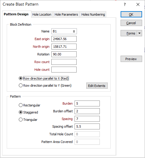
Create Blast Pattern
![]()
If a blasthole design layer is not already set as the active layer, the Select Active Layer dialog is opened by default.
Use the Pattern Design tab of the Create Blast Pattern form, to define a basic rectangular, staggered, or triangular blast pattern. Holes can also be restricted to an outline or a string, to create a non-rectangular blast pattern.
Definition
Define the Name, Location, Rotation and Direction of the pattern.
Name
When creating a pattern, you have the option of specifying a block name. If the block name is unspecified, then the active block name (defined on the Input Data tab of the Blasthole Design form) is automatically assigned to the new pattern.
The specification of an existing block name allows new holes to be added to an existing block.
Note: The block name is used to identify holes corresponding to different blocks in the database. Therefore, it is important that all holes have a block name.
Location
Define the East and North origin of the bounding rectangle.
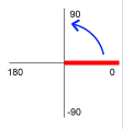
Rotation
Define the rotation of the bounding rectangle. The rotation angle starts from a 90° (right) direction and is measured anti-clockwise.
Number of Rows and Number of Holes
Enter the number of rows and the number of holes. Initially a grid is created using a fixed number of rows and holes, but can be edited interactively in Vizex using Edit Extents (See below).
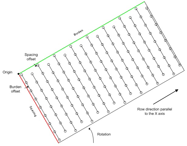
Row direction
Specify whether the row direction will be ![]() parallel to the X axis (the default) or
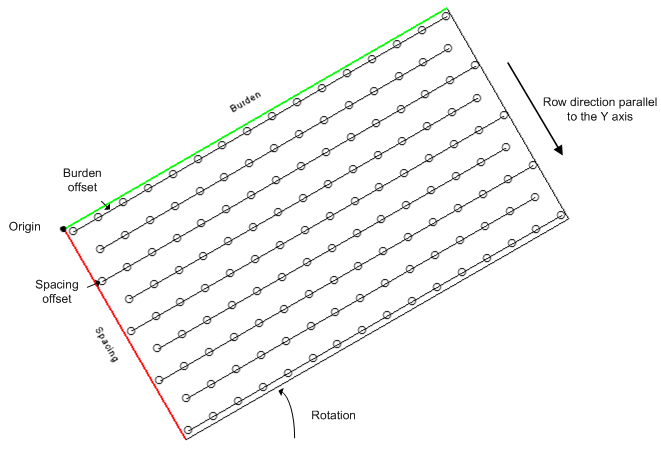
parallel to the X axis (the default) or ![]() parallel to the Y axis. The axes of the blasthole boundary are labelled by Burden and Spacing and the colours drawn on the axes are consistent with the 3D orientation axis in Vizex:
parallel to the Y axis. The axes of the blasthole boundary are labelled by Burden and Spacing and the colours drawn on the axes are consistent with the 3D orientation axis in Vizex:
- Red is the colour for the X-axis:
- Green is the colour for the Y-axis:
Edit Extents
Click the Edit Extents button to collapse the form and visually adjust the extents of the pattern. Interactively adjusting the extents rectangle in Vizex will update the values in the form.
Pattern
Choose whether the blasthole spacing is rectangular, triangular, or staggered. A staggered or triangular drilling pattern is generally considered more efficient than a square or rectangular pattern. See: Patterns
Burden and Spacing
The Burden distance will generally lie between 20 to 35 times the hole diameter depending on the rock density and the explosive charges used. The Spacing distance between blastholes is generally between 1 to 1.8 times the burden, with 1 used for very hard massive rock and 1.8 for very soft or well-jointed rock. See: Burden and Spacing
Burden and Spacing distance values cannot be negative or zero values.
Burden Offset and Spacing Offset
If there is no Burden offset or Spacing offset , then the first blasthole has the Easting and Northing value of the boundary origin.
Note that the reported pattern area corresponds to the area covered by the drillholes in the pattern.
When a Burden Offset or a Spacing Offset value is entered on the Pattern Design tab of the Create Blasthole Pattern form, the extents are automatically modified so that:
-
When a Burden Offset is entered, the first and last row of the pattern are adjusted to maintain the specified offset distance from the adjacent sides of the grid.
-
When a Spacing Offset is entered, the first and last holes in each row are adjusted to be the specified offset distance away from the adjacent ends of the pattern.
Total Hole Count
Displays the total number of holes that will be in the pattern based on the design parameters. The value will be updated as changes are made to the design parameters.
Pattern Area Covered
Displays the total area of the pattern based on the design parameters. The value will be updated as changes are made to the design parameters.
Preview
Click the Preview button to see a preview of the extents of the blast pattern, the collars and traces of the pattern, and the numbering (if specified).
OK
When you have defined a blasthole pattern, defined its location, parameters, numbering, and previewed the result, click OK to create the blast pattern.