Downhole Surveys
Input Requirements
In order to calculate 3D coordinates for the downhole survey points, Micromine Geobank requires the following SQL result set:
| Value | Description |
|---|---|
| NORTHING | Northing of the starting point (drillhole collar) |
| EASTING | Easting of the starting point (drillhole collar) |
| HEIGHT | Elevation of the starting point (drillhole collar) |
| COORDSYS | Identifier for the coordinate reference system used for these coordinates |
| DEPTH | Depth (distance from collar) of the downhole survey point |
| Z_UNITS | Units of measure used for the survey depth (if relevant) |
| DIRECTION | Direction of the hole, measured as the angle clockwise from North, where "North" is represented by a DIRECTION of zero degrees in the target system |
| INCLINATION | Vertical angle in degrees, with -90 degrees being vertically down. |
The SQL query used to generate the result set for the downhole survey calculations can be customised to suit specific requirements and/or a specific data model. It is therefore up to the Micromine Geobank administrator to decide how the data should be stored and to design the SQL query accordingly. Depending on requirements, the administrator may decide to introduce additional metadata tables or columns in order to deal with the complexities of the input data.
The COORDSYS code returned by the query does not hold any special significance to Micromine Geobank with regard to the calculations. It is merely the qualifier that will be stored along with the output (to properly identify the coordinate system of the output coordinates). However, it is important to note that the input value for DIRECTION is assumed to be the angle between the direction of the drilling vector and the direction of the north axis of the target system. In other words, "North" in this case is whatever is North for the specified COORDSYS. For example, if COORDSYS represents a UTM projection, then DIRECTION should be the angle (clockwise) from the UTM north. If COORDSYS is a local grid, then DIRECTION is assumed to be relative to the north axis of the local grid. It is therefore likely that the query will have to use the COORDSYS code to retrieve further metadata relating to the orientation of the coordinate system.
In general, the final value for DIRECTION can be determined as follows:
- Start with the bearing recorded by the measuring instrument
- Add the appropriate offset angle (e.g. magnetic declination) in order to convert this bearing to true north
- Determine the difference between true north and grid north for the target system (i.e. the one we are calculating coordinates for)
- Apply this difference to convert true north to grid north for the target system
As mentioned before, this solution could be implemented in many different ways.
Micromine Geobank Standard Data Model
The Micromine Geobank Standard Data Model provides a very basic structure for the storage of downhole survey data and metadata. The relevant tables, as defined in the current Standard Micromine Geobank Database, are shown.
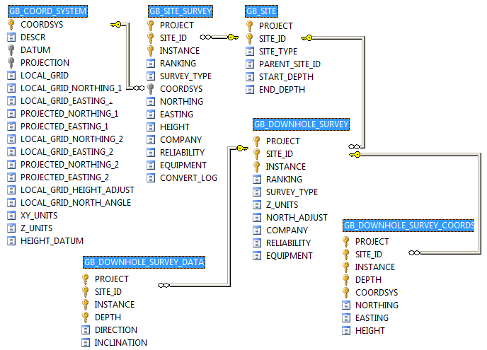
The LOCAL_GRID_NORTH_ANGLE column in the GB_COORD_SYSTEM table is designed to store the angle between True North and the north axis of the grid. Currently this column is not populated automatically by Micromine Geobank and the value defaults to zero. If required, the value must be entered manually (using an appropriate data view).
The same applies to the NORTH_ADJUST column in the GB_DOWNHOLE_SURVEY table. This column is designed to store the angle between True North and the "north" reference used for the direction measurements in the downhole survey. In most cases this value will in fact be the magnetic declination at the surveyed location at the time that the survey was performed.
It is important to store the value for magnetic declination at the downhole survey instance level, because this value is subject to local and temporal variations in the magnetic field.
The basic Micromine Geobank setup should be sufficient to cater for most implementations:
| Table | Column | Description |
|---|---|---|
| GB_COORD_SYSTEM | LOCAL_GRID_NORTH_ANGLE | The rotation angle of the "north" axis of the local grid, clockwise from True North |
| GB_DOWNHOLE_SURVEY | NORTH_ADJUST | The angle between True North and the "north" reference used by the downhole survey (e.g. magnetic declination) |
In this case, the calculation to derive the final value for DIRECTION would be:
DIRECTION = MEASURED_DIRECTION + NORTH_ADJUST – LOCAL_GRID_NORTH_ANGLE
The LOCAL_GRID_NORTH_ANGLE can be used to cater for grid convergence; however, this assumes that the grid convergence is constant over the area of use. Given the fact that a UTM zone is several hundred kilometres wide, this seems to be a reasonable assumption, provided that the drilling program does not cover a very large area. If this solution is not considered accurate enough, then it may be necessary to store the grid convergence value along with the drillhole survey coordinates. (This value is not currently provided by Micromine Geobank and would have to be entered manually.)
The grid convergence is usually added to true north to calculate grid north. To fit in with the convention used for local grids, we would therefore have to change the sign of the grid convergence value.
Say, for example, that we have three COORDSYS definitions:
| CoordSys | Type | Grid Rotation | Offset from True North |
|---|---|---|---|
| UTM1 | UTM projection | 0° | 0.5 (grid convergence = -0.5°) |
| LOCAL01 | Local grid (based on UTM1) | 45° | 45.5° |
| LOCAL02 | Local grid (based on UTM1) | -12° | -11.5° |
Now assume that we have two downhole surveys with DIRECTION measured as follows:
| Instance | North reference used for measurements | Mag declination |
|---|---|---|
| 1 | N-S axis for LOCAL01 | n/a |
| 2 | Magnetic north | 7° |
The following rules would apply to calculate downhole coordinates for the various reference systems:
| Input Instance | Measured Direction | Reference System | Offset from True North | Target CoordSys | Offset from True North | Adjusted value for DIRECTION |
|---|---|---|---|---|---|---|
| 1 | 10 | LOCAL01 | 45.5 | LOCAL01 | 45.5 | 10 + 45.5 – 45.5 = 0 |
| 1 | 10 | LOCAL01 | 45.5 | LOCAL02 | -11.5 | 10 + 45.5 – (-11.5) = 67 |
| 1 | 10 | LOCAL01 | 45.5 | UTM1 | 0.5 | 10 + 45.5 – 0.5 = 55 |
| 2 | 10 | Magnetic | 7 | LOCAL01 | 45.5 |
10 + 7 – 45.5 = -28.5 (i.e. 331.5)* |
| 2 | 10 | Magnetic | 7 | LOCAL02 | -12.5 | 10 + 7 – (-12.5) = 29.5 |
| 2 | 10 | Magnetic | 7 | UTM1 | 0.5 | 10 + 7 – 0.5 = 16.5 |
*This bearing lies in the fourth quadrant relative to the LOCAL01 grid axes and should therefore be expressed as 360 – 28.5 = 331.5 degrees.
Using more elaborate models and methods
As mentioned before, it is up to the Micromine Geobank administrator to decide how the downhole survey data should be stored and applied.
Some Micromine Geobank clients have elected to store several versions of downhole survey data, based on various UTM or local grids. Others have chosen to use tables containing magnetic declination readings over time. Some may decide to maintain a more accurate record of grid convergence for various areas.
Whatever the implementation may be, Micromine Geobank is flexible enough to deal with it.