Coordinate System Tables
Coordinate reference systems play a fundamental role in Micromine Geobank. Whenever Micromine Geobank processes a set of coordinates, it expects these coordinates to be qualified by a predefined coordinate reference system.
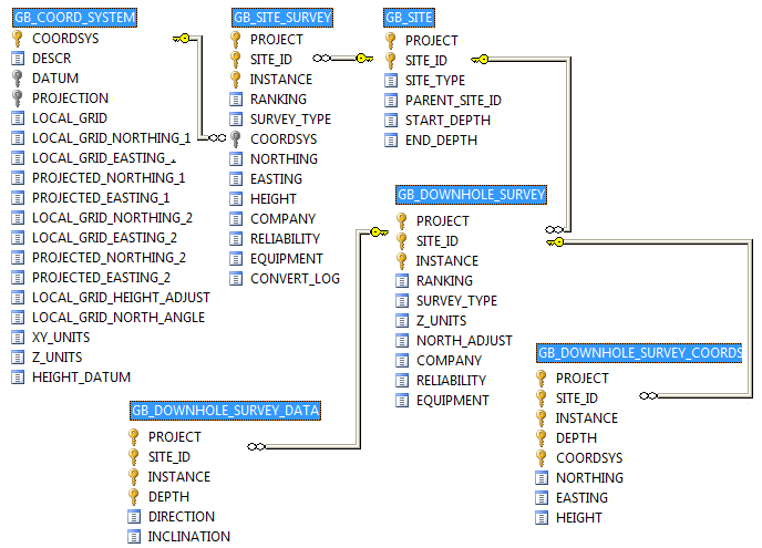
Coordinate reference system definitions are stored in the GB_COORD_SYSTEM table, which in turn is linked to several metadata tables.
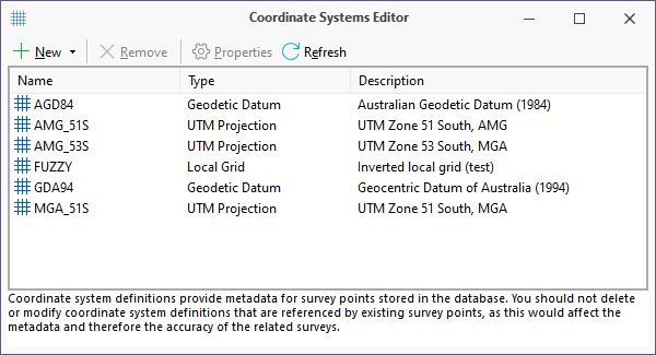
Occasionally it may be necessary to add a datum definition or spheroid parameters to the system tables. However, user interaction should normally be limited to the GB_COORD_SYSTEM table, which is maintained via the Coordinate Systems Editor.
The structure of the GB_COORD_SYSTEM table is as follows:
| COORDSYS | A unique code used to identify the reference system. |
| DESCR | The name of the reference system, as displayed in pick lists in the Micromine Geobank interface. |
| DATUM | A code identifying the geodetic datum on which the reference system is based. |
| PROJECTION | A code identifying the UTM projection. If this column contains the word NONE, the reference system is assumed to be geodetic. |
| LOCAL_GRID | A short name identifying the local grid, if applicable. Enter the word NONE in this column if the reference system does not include a local grid component. |
| LOCAL_GRID_NORTHING_1 | A local grid is defined by providing accurate coordinates for two control points on diagonally opposite corners of the study area. Northing and easting pairs for each point must be supplied in both local grid and projected (UTM) coordinates. The local grid northing for the first control point is entered in this column. |
| LOCAL_GRID_EASTING_1 | Local grid easting for the first control point. |
| PROJECTED_NORTHING_1 | Projected (UTM) northing for the first control point. |
| PROJECTED_EASTING_1 | Projected (UTM) easting for the first control point. |
| LOCAL_GRID_NORTHING_2 | Local grid northing for the second control point. |
| LOCAL_GRID_EASTING_2 | Local grid easting for the second control point. |
| PROJECTED_NORTHING_2 | UTM northing for the second control point. |
| PROJECTED_EASTING_2 | UTM easting for the second control point. |
| LOCAL_GRID_HEIGHT_ADJUST | This value represents the height difference between the projected and the local grid, i.e. ?h where Local Height = UTM Height + ?h. |
| XY_UNITS | Identifies the units of measurement for the easting and northing coordinates (as defined in the table GB_SYS_UNITS_LENGTH). |
| Z_UNITS | Identifies the units of measurement for the height coordinate. |
| HEIGHT_DATUM | Identifies the height datum used for the height measurement. Height datum conversions are not supported in the current version of Micromine Geobank and therefore this column has no effect at present. (All heights are assumed to be orthometric.) |
| LOCAL_GRID_NORTH_ANGLE | This column is not used directly by Micromine Geobank but is retained for reporting purposes. It specifies the orientation of the local grid relative to true north. |
The metadata tables are listed below:
| GB_SYS_CS_DATUM | Contains metadata for geodetic datums referenced by coordinate systems. |
| GB_SYS_CS_ELLIPSOID | Contains metadata for spheroids referenced by geodetic datums. |
| GB_SYS_CS_PROJECTION | Contains metadata for Universal Transverse Mercator (UTM) zones, which are used as a basis for map projections. |
| GB_SYS_CS_SHIFT_GRID | Optional table containing the header information for coordinate shift (distortion) grids used in geodetic datum transformations. |
| GB_SYS_CS_SHIFT_NODE | Optional table containing the latitude and longitude offset parameters for individual nodes in the distortion grid. |
| GB_SYS_UNITS_LENGTH | Metric conversion factors for various units of measure (distance). |
The meaning of individual columns should be clear to anyone with a basic knowledge of geodesy. One important aspect should be mentioned however. Both the datum table and the projection table carry columns to indicate the orientation of the coordinate axes. The Micromine Geobank convention is based on the following assumptions:
- Latitude is positive in the northern hemisphere and negative in the south
- Longitude is positive in the eastern hemisphere and negative in the west
- Northing increases from south to north
- Easting increases from west to east
In countries like Canada, for example, the INVERT_LONGITUDE column in the GB_SYS_CS_DATUM table should be set to "Y" to indicate that longitude is reported as positive in the western hemisphere.
Similarly, a coordinate reference system defined in South Africa would use the INVERT_EASTING and INVERT_NORTHING flags to define the orientation of the local LO system.
The COORDSYS column plays a very important part in Micromine Geobank. It is used throughout the system to link coordinates to a coordinate reference system.
Using Datum Transformation Grids
Micromine Geobank supports the use of “block shift” grids to transform coordinates between geodetic datums. This method ensures a high degree of accuracy and is therefore strongly recommended.
Transformation grids are stored in two tables in the Micromine Geobank database.
![]()
This structure is based on the Canadian National Transformation Version 2 (NTv2) format, which has become an accepted standard in several countries. For example, Australian government agencies use this format to distribute national transformation grids for public use.
Micromine Geobank does not support the direct manipulation of NTv2 files; however, utilities to convert NTv2 grids to text files can be downloaded from the Internet.